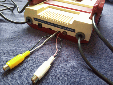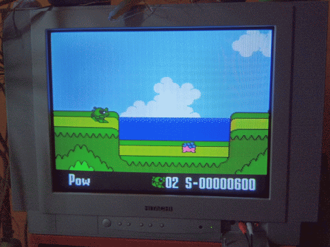
Connecting an original Nintendo Famicom to a television in the West can be problematic, especially in the modern times. An AV-mod could solve this problem for you and as a bonus the AV-output will give you a lot better image and sound quality than the original RF-output. In this guide I will teach you how to perform an AV-mod on a Famicom (version HVC-CPU-07). If you don't know which version you own, I will help you find out in part A of this guide.
My modding method is an adaptation of the method used by Famicomania and I'd like to give credit where credit is due. My method requires no drilling or any other irreversible changes to the Famicom and all chosen soldering points are low risk. That being said, Famicoms are fragile, so follow this guide at your own risk. Now with the introduction out of the way, let's get started!
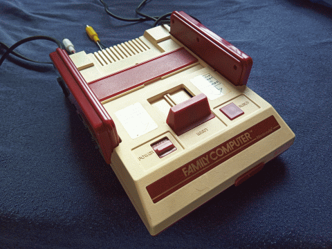
Required parts
2x Female RCA-plug (preferably 1 yellow and 1 white);
4x Wire (preferably in 3 different colors);
1x Transistor 2SC1815;
2x Resistor 22 kΩ;
1x Electrolytic capacitor 0,47 μF 50 V.
![]() Part A - Disassembly
Part A - Disassembly
Step 1 - Case
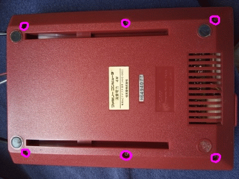
Open the case by removing 6 screws on the bottom of the console.
Step 2 - Motherboard
Free the motherboard by removing 4 screws.
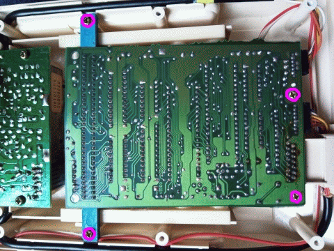
Step 3 - RF-module
Free the RF-module by removing 4 screws.
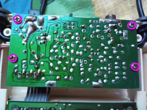
Step 4 -
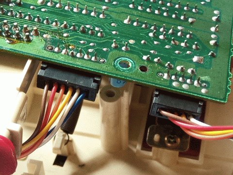
Controller cables
Disconnect the controller cables from the motherboard. You can put your
nails or a screwdriver in the little gaps on the side and pull. These
connectors can be tough and some force may be needed, but be gentle, as
you don't want to damage the solder joints on the motherboard.
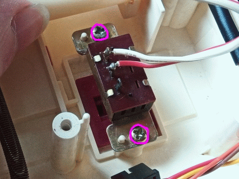
Step 5 -
Power switch
Push the game ejector out of the way with your thumb and free the power
switch by removing 2 screws with your other hand.
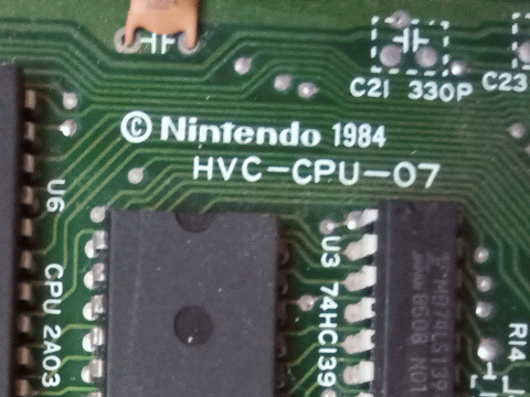
Step 6 - Check your version
At this point you should be able to take the motherboard and the RF-module
out of the case. Now look at the white text on the top of your
motherboard. If it says exactly "HVC-CPU-07", then your Famicom is
compatible and you can proceed with this guide. If it says something
else, then your Famicom is probably incompatible and you should look for
another guide.
![]() Part B - Soldering on the motherboard
Part B - Soldering on the motherboard
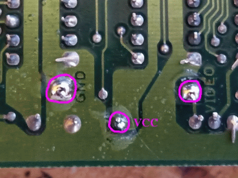
Step 1 - Preparing the video joints
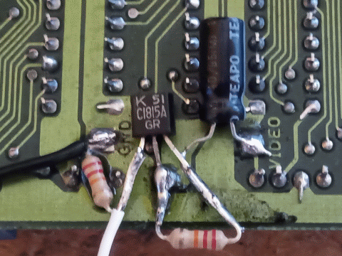
Add some flux and solder to the GND, VCC and VIDEO joint. These joints
are located on the bottom of the motherboard.
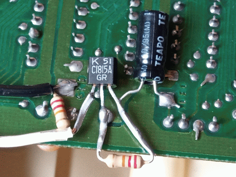
Step 2 - Capacitor
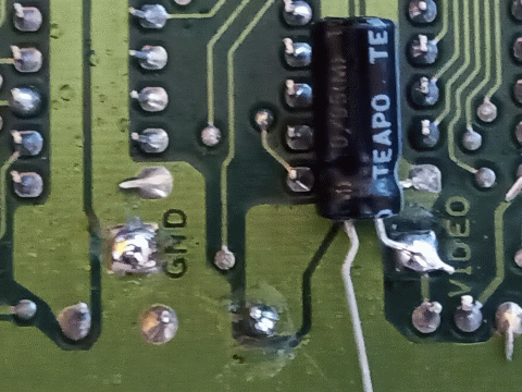
Cut the negative leg of the capacitor to the appropriate size and
carefully bend it in the right position. Then solder it onto the VIDEO
joint. The negative leg of the capacitor is the shorter leg.
Step 3 - Right leg of the transistor
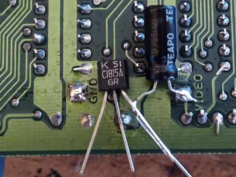
Carefully bend the positive leg of the capacitor and the legs of the
transistor to the appropriate positions. Then solder the positive leg of
the capacitor onto the right leg of the transistor. The text of the
transistor should be facing you.
Step 4 - Center leg of the transistor
Solder the center leg of the transistor onto the VCC joint.
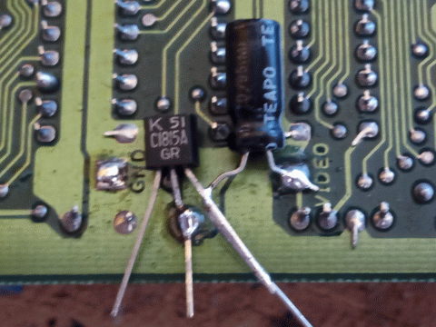
Step 5 - Resistor I
Cut the center and the right leg of the transistor and both legs of a
resistor to the appropriate size. Then carefully bend the legs of the
resistor in the right position and solder it between the right and the
center leg of the transistor.
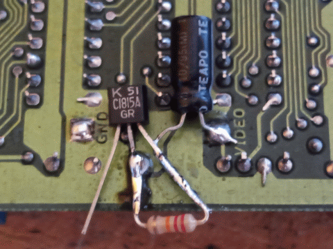
Step 6 - Resistor II
Cut the left leg of the transistor and both legs of the other resistor
to the appropriate size. Then bend the legs of the resistor in the right
position and solder it between the left leg of the transistor and the
GND joint.
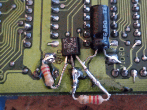
Step 7 - Video wire
Cut a long piece of white wire (or another color) and solder it onto the
left leg of the transistor. This will be our video wire.
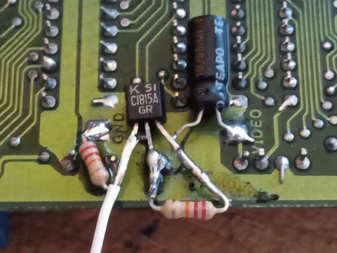
Step 8 - Ground wire
Cut a long piece of black wire (or another color) and solder it onto the
GND joint. This will be our ground wire.
Step 9 - Preparing the audio joint
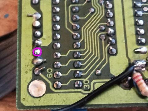
Add some flux and solder to the circled joint. This
joint is located on the bottom of the motherboard near the ribbon cable
that leads to the RF-module.
Step 10 - Audio wire
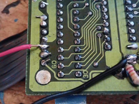
Cut a long piece of red wire (or another color) and solder it onto the
above joint. This will be our audio wire.
Step 11 - Check your work
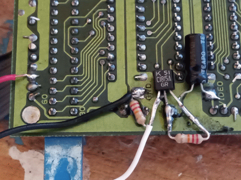
Check whether all the connections have been soldered as they should.
Also check if none of your soldering connections are making false
contact with any motherboard joints they shouldn't be making contact
with.
![]() Part C - Reassembly
Part C - Reassembly
Step 1 - Clean up
Clean up all the flux around your solder joints. I use 96% pure alcohol
ketonatus for this. Don't forget to clean up around the audio joint as
well.
Step 2 - Direct the wires
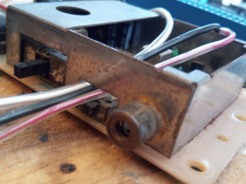
Direct the 3 wires to the outside through the hole above the channel
switch. The channel switch is located on the RF-module. Don't put too
much stress on the wires, as you don't want to damage your soldering
work.
Step 3 - Secure the wires
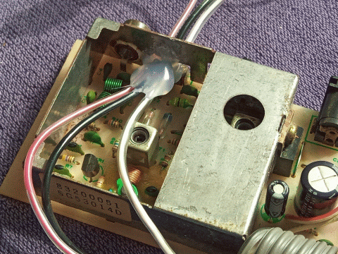
Put a glue blob with a glue gun on the wires near the hole above the
channel switch. This will protect the soldering connections on the
inside from outside stress.
Step 4 - Reassemble the
console
Put the Famicom back together. Follow the steps 1-5 from part A in
reverse.
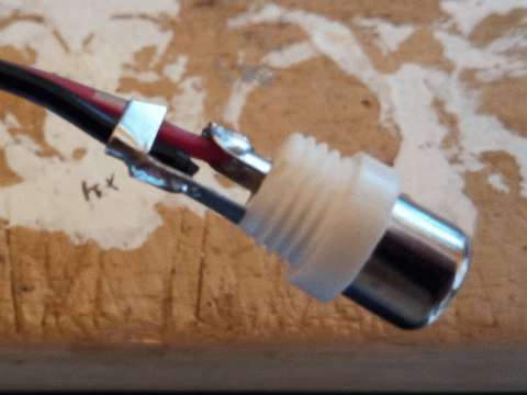
![]() Part D - Soldering the RCA-plugs
Part D - Soldering the RCA-plugs
Step 1 - Shells
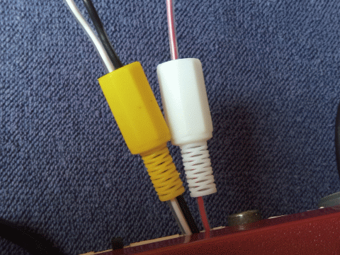
Open the RCA-plugs and separate the shells from the tips.
Push the yellow shell over the white and the black wire and the white
shell over the red wire.
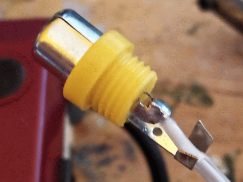
Step 2 - Video plug center
Solder the white wire onto the center of the yellow RCA-tip.
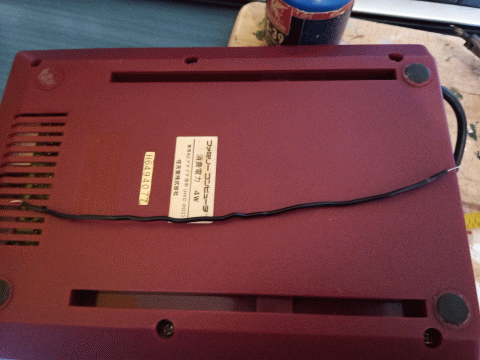
Step 3 - Ground bridge
Cut an extra piece of black wire. We will use this wire to bridge the
ground from the video plug to the audio plug.
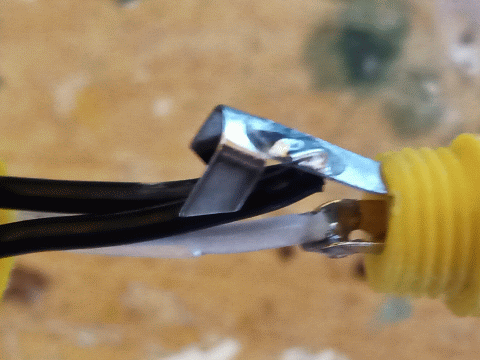
Step 4 - Video plug ring
Push the bridge wire through the yellow shell. Then solder both the
ground wire and the bridge wire onto the ring of the yellow RCA-tip.
Thereafter you can secure the wires by squeezing the metal brace and
close the yellow plug.
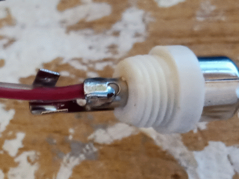
Step 5 - Audio plug center
Solder the red wire onto the center of the white RCA-tip.
Step 6 - Audio plug ring
Push the bridge wire through the white shell. Then solder the bridge
wire onto the ring of the white RCA-tip. Thereafter you can secure the
wires by squeezing the metal brace and close the white plug.
![]() Part E - End results
Part E - End results
Congratulations! You should be ready now to enjoy your new
AV-output.
